Analysis of the electric field of an electroplating cell with Ansys
Sector: Electrical engineering/electronicsSpecialist field: MultiphysicsAtotech commissioned CADFEM to perform a nonlinear simulation analysis of the electroplating process to determine the current density distribution and the expected coating thickness.
Summary
Task
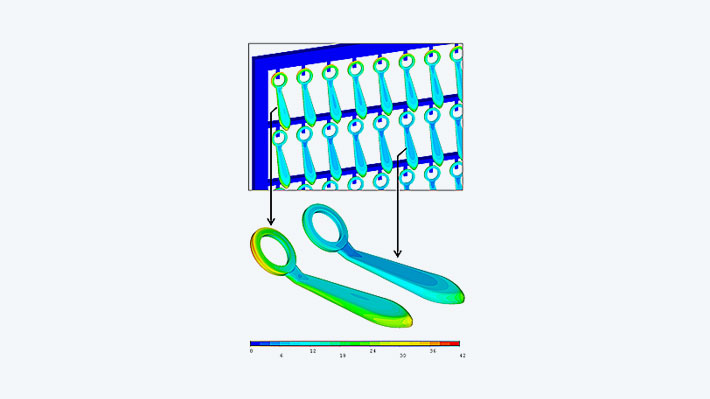
In an electroplating process, the local thickness and quality of the electroplated layer depend on the local electric current density on the surface of the parts. CADFEM analyzed the current density distribution over the parts using an electric field analysis and calculated the resulting layer thickness.
Solution
After applying the given cell voltage or current, the FEM analysis in Ansys provides the current density distribution on the parts. The resulting local coating thickness is finally calculated from the local current density, the given coating time and various coefficients.
Customer benefits
The simulation enables the optimization of the electroplating cell and the parts.
Project Details
Task
In an electroplating process, the local thickness and quality of the electroplated layer depend on the local electric current density on the surface of the parts. Typically, the current density is highest at edges and lowest in recessed areas of the surface. The current density distribution over the parts is analyzed using an electric field analysis and the resulting coating thickness is calculated.

Customer Benefit
Simulation allows optimization of the plating cell and parts:
- Prediction of variations in coating thickness and quality across the parts associated with positions of the frame.
- Analysis of the interaction between multiple parts in an electroplating cell.
- Design of anode shapes, non-conductive shields, or modification of parts for optimal plating conditions.
- Reduction of coating material consumption by homogenization of layers.

Solution
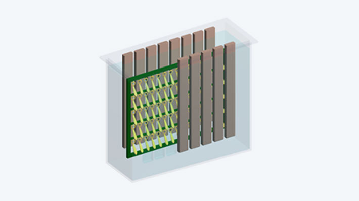
To calculate the current conduction field, an FEM model is created in Ansys from the electrolyte volume of the electroplating cell. This FEM mesh is assigned the conductivity of the electrolyte as a material property. A local potential reduction occurs at the boundary between metallic parts and an electrolyte, which has a nonlinear relationship with the local current density. This boundary potential is called "overpotential". It affects the current density distribution across the parts and must be determined in a laboratory for each specific combination of metal surface and electrolyte. Once this function is known, it can be implemented in the simulation as a nonlinear surface boundary condition. After applying the given cell voltage or current, the FEM analysis provides the current density distribution on the parts. The resulting local coating thickness is finally calculated from the local current density, the given coating time and various coefficients.
Images: © Atotech


