Mubea uses Ansys optiSLang to optimize coil springs
Results as light as a feather
The family-owned company Mubea is regarded as an innovative lightweight specialist for heavy-duty spring and vehicle components. In order to develop the optimal products quickly and economically, Mubea Fahrwerksfedern GmbH uses optimization software embedded in the simulation that can do more than just test a model for strength.
Lightweight design specialist Mubea
In the more than 100-year history of the company, a number of Mubea innovations have been made in the automotive industry. For example, the world’s first tubular stabilizer was developed in Attendorn in 1980 on behalf of Porsche. The weight reduction compared to the previous solution was 40% and was immediately used in series production for the Porsche 928 model.
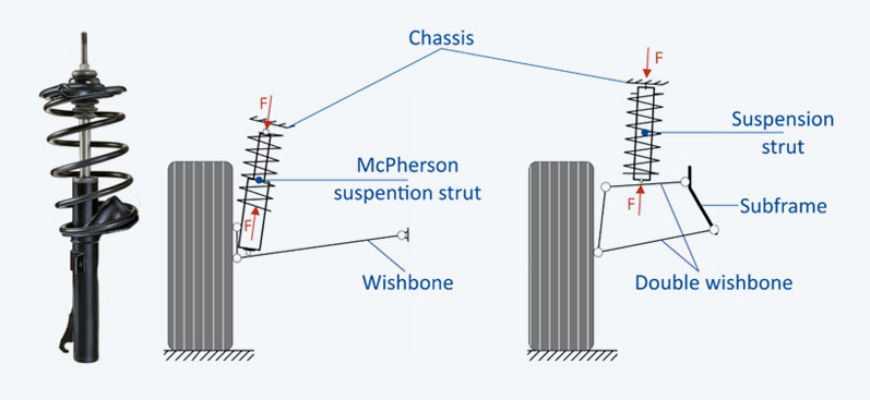
Or when the Volkswagen Group reached its limits with conventional McPherson struts in the Audi Quattro, Golf and Passat models at the end of the 1980s, Muhr and Bender came up with the patented “side-load spring”. Today, this spring, also known as the force-medium-point (KMP) spring, is a valuable standard. The spring, which is s-shaped when unloaded, can handle lateral forces and is essential for the functionality of the overall system in modern vehicles. The design of such a spring is extremely demanding and production requires the utmost care. Even small errors can result in high consequential costs due to axle damage.
Driving comfort and safety
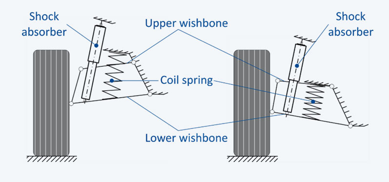
Regardless of whether coil springs are installed in vehicles with conventional or electric drive systems, they have a major influence on driving comfort and safety. Although hardly visible, the coil springs, in combination with stabilizers, have a decisive influence on “the good feeling” in vehicle handling, safe road holding and controlled braking behavior, which is what makes relaxed driving possible in the first place. Experts refer to this as “roll and pitch response”.
For Mubea’s recognized quality promise, the control of all factors influencing the final product is of the utmost importance. As a defined lightweight specialist, it is always important to choose the materials and the construction method in such a way that, on the one hand, the variety of requirements can be met while, on the other hand, the loads that occur can be withstood without generating unnecessary ballast. The structure as a family business, with a great deal of expertise and a high level of vertical integration, provides the necessary flexibility and speed that the market demands.

Simulation goes without saying
The foundation for the safety and competitiveness of a future successful coil spring system is already laid out in the development department. This is where the implementation of numerous and groundbreaking innovations takes place. It therefore goes without saying that at Mubea, simulation software is used to efficiently check the load capacity of design variants.
Sergej Schneider, engineer for simulation technology at Mubea Fahrwerksfedern GmbH, knows what is important. He explains, “for cylindrical coil springs, where the force is applied in parallel, the design can perhaps still be carried out using analytical formulas. However, simulation is essential for the economical and timely design of KMP springs, which are subject to lateral forces and have various coil spring and deflection shapes”.
Sergej Schneider, Head of CAE Chassis Advanced Development, Mubea Fahrwerksfedern GmbHWith Ansys optiSLang, automated design is convincing through high-quality results in the shortest possible time and by finding sensible solutions, especially where manual design is difficult.
Graphical Spring Designer
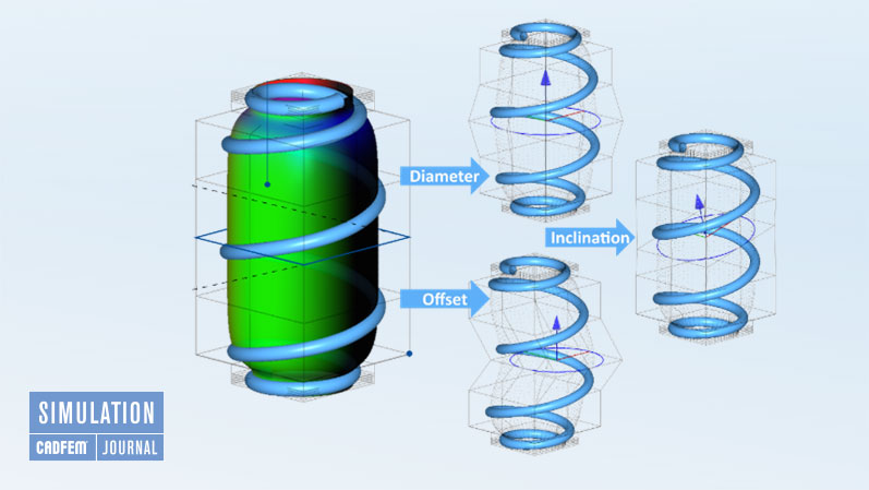
The coil spring modeling takes place in a specially inhouse developed app called “GRASP-Designer”. The application provides a cylindric jacket as an auxiliary geometry around which the spring winds in a helix with a constant pitch. It is sufficient to enter a few parameters in order to be able to create the design of c- or s-shaped coil springs with cylinder bodies and coiling of varying complexity. The mathematical construct of NURBS (Non-Uniform-Rational-B-Splines) was used to define the cylinder and coiling data. This is an extension of the B-splines definition, which can mathematically represent ideal circular curves, and is a crucial requirement in obtaining the most meaningful simulation data possible.
The lateral surface of the parametric cylindrical body is thus defined as a closed NURBS surface and is provided with control points that represent a control network that operates in the background and allows calculations. In the design process, not all control points are released as parameters, but rather only so-called “substitutes” as a meaningful summary of points. These are very intuitively identified as diameter, offset and inclination and reduce the optimization parameters.
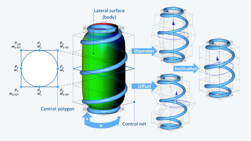
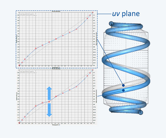
The multi-coiling of the coil spring on the cylindrical body is achieved by a variable number of control points and the desired number of coils. The first and last control points are fixed, all other points can be moved freely in the uv plane (u = coiling direction, v = “height” on the lateral surface). The local influence of a control point of the coil on the coil spring geometry depends on the degree of the NURBS curve (see Figure).
Specialty Optimization
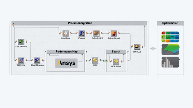
In addition to the customary numerical simulation, which is carried out at Mubea using a beam model and a solid model, the possibility of design optimization is particularly important. While the FE analysis is covered by Ansys Mechanical APDL (Ansys Parametric Design Language), Ansys optiSLang is responsible for the optimization. As an alternative to the optimization within the simulation, testing with prototypes is available. However, considering the numerous variants and the high expenditure in terms of material, time and manpower, the question of economic efficiency quickly arises. With Ansys optiSLang, designs can be understood and evaluated quickly as well as improved very cost-effectively in the shortest possible time. This is an advantage that a medium-sized company like Mubea is happy to take advantage of in order to achieve rapid market maturity for high-quality products.
Check 4000 variants at the push of a button
Coil springs are subject to both static and dynamic loading during compression and extension, and they take up space in the process. The static load is evaluated on the basis of the shear stress, the dynamic load on the basis of the damage parameter according to Smith, Watson and Topper. In addition to the restrictions of not exceeding the set limit stress and damage, the primary goal is to homogenize either shear stress or damage over a considered coil area of the coil spring and thus use the material evenly. In addition, attention is paid to possible damage to the installation space in which the coil spring is located. With Ansys optiSLang, such an automated coil spring design can be carried out without any problems.
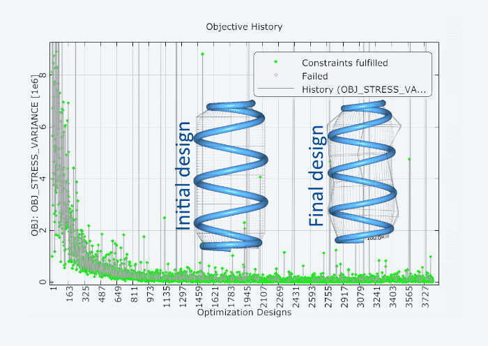
In the example shown, a cylindrical coil spring based on an analytical preliminary design has been used. After simulating almost 4000 designs, the final optimized design was determined. At Mubea, optiSLang usually checks between 4,000 and 6,000 designs until the best variant is determined.
Virtual Beats Manual
For Mubea simulation engineer Sergej Schneider, design optimization with Ansys optiSLang has become indispensable: “The automated design of coil springs with optiSLang has proven itself at Mubea and is extremely practical. Automated design is convincing in two respects: through high-quality results in the shortest possible time and by finding sensible solutions, especially where manual design is difficult. The great advantage of automated design lies in the homogenization of the stress and, in particular, damage curves, which otherwise pose a major challenge in manual design.”
The simulation and optimization tools of Ansys, in conjunction with the support of CADFEM, offer Mubea an indispensable help in finding the optimum variant for perfect lightweight construction.

Authors:
Thomas Löffler (free Editor)
Sergej Schneider (Mubea)
Images: © Mubea
Published: September, 2022
Contact CADFEM


