Tech Article | 23/09
Hydrogen instead of natural gas: Optimal burner geometry through CFD simulation
Do you have an industrial burner that runs on natural gas and want to switch to hydrogen? That sounds like a good idea, because hydrogen is a clean and renewable energy source that can reduce CO2 emissions. But can you simply use the same burner? How can you find this out without investing lots of money and time? Learn more about the possibilities of CFD simulation in this article and get inspired by practical tips on grid generation, combustion models, and the new GPU solver.
Why should I simulate combustion?
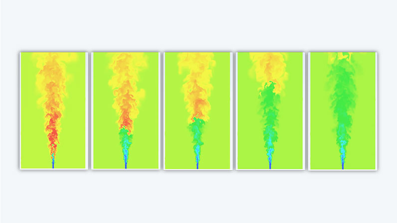
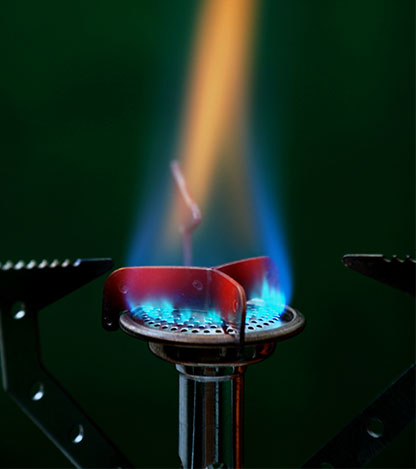
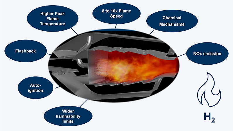
Hydrogen has different physical and chemical properties than natural gas. As a result, the combustion of hydrogen also behaves differently than that of natural gas. For example, hydrogen has a higher flame speed, a lower ignition temperature, and a higher reactivity. This has an impact on the stability, efficiency, and emissions of the flame. So, if you simply use the same burner that is actually designed for natural gas, you might not achieve the desired performance or may even have safety issues.
For example, there may be a flashback, auto-ignition, or incomplete combustion. This can lead to increased consumption of hydrogen, reduced heat transfer, or increased formation of nitrogen oxides (NOx). To avoid this, it is advisable to adapt the burner for hydrogen. This includes changing the fuel-air ratio, the pressure, the temperature, or even the geometry of the burner. Perhaps you also want to analyze how different mixing ratios of natural gas and hydrogen behave? But how do you find out which parameters you need to change?
This is not so easy to answer, because the combustion of hydrogen is a complex process that depends on many factors. With a powerful simulation tool, you can virtually model the flow, combustion, and heat transfer in your burner and test various scenarios. This allows you to find the optimum configuration for your burner before you use it in reality.
How can CFD simulation help me?
This is where Ansys Fluent comes into play for CFD simulation. CFD stands for Computational Fluid Dynamics and is a method of numerically calculating the flow of gases and liquids. CFD simulations allow you to virtually simulate your burner and vary various parameters. This allows you to see how the flow, combustion, and heat transfer in your burner behave and what effects this has on performance and emissions. You can also compare different burner designs and choose the best one.
Other benefits of CFD simulation of industrial burners include:
- Saving money and time: No need for real tests with expensive prototypes.
- Increase safety: Predict and avoid flashback and spontaneous combustion.
- Improve efficiency and environmental compatibility: Optimize fuel-to-air ratio and reduce NOx emissions.
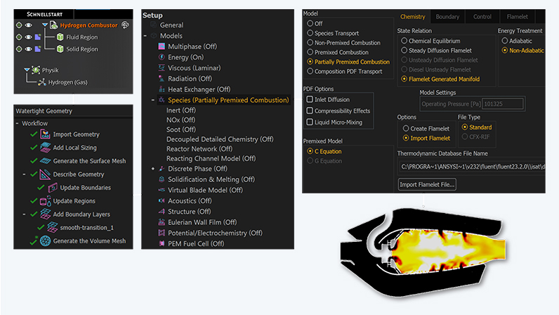
Simulate combustion - Start with the grid
Once you have mastered the first steps and clearly outlined your task, it is worth focusing on grid generation. The grid consisting of individual cells has a significant influence on the accuracy and stability of the simulation. A high-quality grid should always have the following properties:
- Sufficient resolution to capture all relevant flow structures,
- smooth transition between regions to reduce the numerical error, and
- an alignment of the cell surfaces that is as orthogonal as possible to the streamlines.
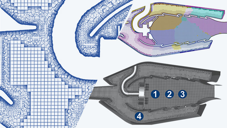
So, what does a suitable grid for hydrogen combustion look like? Here are a few tips for optimal grid generation [1]. The table below provides an orientation of important grid settings for the burner itself including nozzles for the inflow of reactants, for the combustion chamber and its core as well as for the outer areas where no reaction takes place. In detail, every CFD simulation always requires a sensitivity study to minimize the influence of the grid resolution. If turbulent structures of the flow and the interaction of chemistry and flow are to be calculated in particular detail, a much finer mesh may also be required.
By the way: The MOSAIC Poly Hexcore technology patented in Ansys Fluent provides you with a high-quality structured mesh in the combustion chamber, which can also be calculated excellently on a cluster. And with the Fault-Tolerant Meshing Workflow, you can also mesh difficult and complicated CAD geometries, as the method provides automatic correction mechanisms. If you are not sure about the required mesh resolution or just want to resolve the flame front more precisely, you can use the adaptive meshing for polyhedron meshes (PUMA algorithm). A predefined criterion based on the so-called Flame Indicator refines the mesh only where necessary [2].
1. Burner and combustion chamber | A body of influence (BOI) in the burner refines the mesh so that there are at least 20-25 cells above the diameter. It is best to extend the BOI into the combustion chamber by 3-4 times the burner diameter. | |||||
2. Combustion chamber core | The BOI ensures a high-quality and uniform grid in the core and thus improves the resolution of the mixture, flame front, and emissions. | |||||
3. Inlet nozzles of the burner | 8-10 cells above the hole diameter are sufficient to predict whether the flame may go out. | |||||
4. External areas | The resolution outside the core can be coarser, ideally about twice as large as in the core. | |||||
To create a grid inside a hydrogen burner, the combustion chamber can be divided into different areas.
Which combustion model is the right one? EDC vs. FGM model
We now come to the selection of the appropriate combustion model. This should be chosen so that it sufficiently and accurately describes the chemical reactions and the turbulence-chemistry interactions. Common models are the EDC (Eddy Dissipation Concept) and the FGM (Flamelet Generated Manifold). The EDC model is based on the idea that chemical reactions take place in the finest turbulent eddies. The reaction rate is influenced by the vortex size and frequency, which in turn depend on the turbulence. Specifically, the EDC model utilizes an extensive reaction mechanism and solves the reaction equations using efficient tabulation algorithms such as the ISAT (In-Situ Adaptive Tabulation Algorithm).
In contrast, the FGM model is based on the assumption that the internal flame structure follows a one-dimensional representation. This is calculated and tabulated in advance using a laminar 1D flame solver such as Chemkin. The FGM model can, for example, be combined with the skeletal reaction mechanism, which contains 10 gas components (the so-called species) and 25 reactions. If the reaction scope is not sufficient, the UCSD mechanism (57 species, 268 reactions) is an alternative. The following table compares the EDC and FGM models. The table below provides an example setup for the FGM model for a partially premixed flame, as well as recommendations for numerical settings. Sufficiently large flow times ensure a meaningful transient averaging of the results.
When we talk about combustion, we also need to consider the turbulence model. For cases with stable flow fields, RANS models (k-ω SST, Realizable k-ϵ) are an efficient solution for many engineering problems. However, there is often a strong coupling between flow and reaction. For example, unstable flows lead to local extinction of the flame. In order to capture flame formation and pollutant emissions as accurately as possible, a Large Eddy Simulation (LES) is the best choice. However, LES is generally considered to be very complex. A good compromise between accuracy and effort is the Stress-Blended Eddy Simulation (SBES), because it can switch between RANS and LES models.
A comparison of the EDC and FGM combustion models:
| Combustion Model | Advantages | Disadvantages | |||||
| Eddy Dissipation Concept (EDC) | Good for complex chemistry or multiple fuels as it uses detailed reaction mechanisms. | Requires more calculation time as it needs to solve chemical equilibria permanently. Does not account for flame structure, so may have difficulty capturing flame propagation or extinction. | |||||
| Flamelet Generated Manifold (FGM) | Advantageous for applications with fast reactions or partial premixing, such as gas turbines or process furnaces, due to low calculation times. | May have difficultly capturing flashback or detonations. Requires more memory to tabulate flame structure. | |||||
Example setup: Hydrogen combustion with the FGM model for a partially premixed flame:
| Turbulence | Combustion | Reaction mechanism H2 | Flow times (transient evaluation) | |||||
| LES (Dynamic Smagorinsky), SBES | FGM & Finite Rate Model | Skeletal | 3-4 (initialization), 7-8 (statistics) | |||||
| Discretization | p-u-coupling | time step & sub-iterations | ||||||
| Momentum: Bounded Central Differencing, Other: 2nd-order upwind | Time: Bounded 2nd order implicit | SIMPLEC | 1e-5s, 10 It. | |||||
And now? Simulating with the GPU Solver in Ansys Fluent
Detailed and complex methods such as EDC and LES require large computing capacities. But what can be done if no high-performance cluster is available? The new GPU solver in Ansys Fluent offers the solution here, as the calculation can be carried out entirely on one or more graphics cards. This makes it possible to accelerate the computing time many times over compared to conventional CPU solvers, which not only saves time but also leads to considerable energy savings. With a growing variety of models in the GPU solver, engineers are thus able to perform complex calculations in record time, enabling not only precise results but also comprehensive variant studies.
In addition to combustion and turbulence models, other physical aspects can of course be added: Radiation and its effect on the reaction rate, for example, plays a central role. The same applies to coupled thermal simulation in order to determine mechanical component loads or acoustic simulation. Furthermore, the injection or decay of sprays is an exciting CFD topic for which advanced modeling approaches such as the VOF-to-DPM model are available. In order to strengthen confidence in the calculation results, reference is also made to numerous comparisons with experiments [3].
Would you like to dive deeper into all these phenomena? Take part in a special CADFEM training course, e.g. on combustion [4] or turbulence [5], because modern simulation methods open up great perspectives for engineers for faster, more accurate and more efficient simulations, especially for the use of hydrogen in burners, turbines, or furnaces. So, does your burner also work with hydrogen instead of natural gas? Find out with simulation and CADFEM!
Author

Published: January 2024
Editor
Dr.-Ing. Marold Moosrainer
Head of Professional Development
Cover images:
Left: © CADFEM GmbH
Right: © Adobe Stock
References
[1] 5 Best Practices for Hydrogen Gas Turbine Combustor Meshing Using Ansys Fluent
[2] How to Accelerate Ansys Fluent Simulations with Adaptive Meshing
[3] Accelerate Hydrogen Adoption Using Simulation
[4] Combustion and Reactive Flows with Ansys Fluent | Training (cadfem.net)
[5] Turbulence Models for Typical CFD Scenarios | Training (cadfem.net)


