Tech Article | 23/03 Ansys Material Designer: The Digital Material Lab
Material data as desired: Want more Young's modulus?
Have you ever wanted to design a material according to your own ideas? A higher Young's modulus would be nice, wouldn't it? The way to achieve this is through the microstructure of the material. In this article, we look at how you can use Ansys Material Designer to determine the glass particle fraction that will allow you to double the Young's modulus of a plastic.
From microstructure to material parameters
Be it the well-known metal consisting of its crystals or the complex polymers with their cross-linked and entangled molecular chains, all materials have an internal structure. We as engineers combine different materials and create high-performance composites through particle or fiber reinforcement that meet our requirements. Whether we can see the structure of the material or not, it defines all the properties. Of course, it would be great if we could immediately derive quantities for simulation from knowledge of the microstructure. But unfortunately, it's not that easy, unless you happen to know off the top of your head how big the yield stress is at a grain size of 10 µm.
Fortunately, we do not need parameters such as grain size in our deep drawing analysis. However, Ansys requires inputs such as the hardening curve or orthotropy constants. So how do we get the data we need? The ideal solution is surely to ask a gifted physicist who solves the problem with virtuoso integral calculus based on the natural constants alone. If you don't have someone like that, the obvious and unfortunately very expensive way is to experiment by making samples for each variant of the microstructure and testing them. In addition to the high costs, the number of feasible tests is limited, and desired properties cannot be determined at all.
With limited mathematical and financial possibilities, however, there is a way out: simulation! It is now widely used to create FE models, so-called representative volume elements (RVEs), of the microstructure. The idea is captivating. The behavior of the constituents, such as polyamide and glass of a particle-reinforced plastic, can be determined quite inexpensively. To answer the question of what effect 10% or 30% glass particle reinforcement has, we simply simulate tensile, compression, shear tests in various directions as desired. These "synthetic" measurement data can be used to determine the composite properties. This is called homogenization.
What does the homogenization workflow look like?
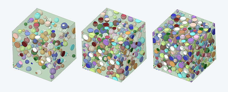
Using particle reinforcement as an example, we will briefly describe the steps involved in homogenization. The first, and by far the hardest point, is the creation of the geometry. RVEs are often modeled as cuboids representing a periodic section of material. First, questions must be answered such as, what shape should the particles be and are they all the same size or is there a distribution function? Then the particles have to be placed collision free in the RVE and this has to be done considering the volume fraction and the periodicity. Since some particles are cut by the edges, more complex geometric shapes are created even for spheres.
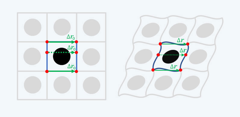
Once the geometry is created, it must be meshed. Of course, one would like to have a periodic mesh that is conformal at the matrix-particle interfaces to avoid contacts. The main headache is small gaps between particles that create small elements. Since a periodic mesh alone does not produce a periodic result, so-called periodic boundary conditions are applied. These are coupling equations between nodes on opposite intersection surfaces. In this way, one can ensure that the deformed RVE can also be lined up exactly periodically. How to avoid overconstraints at the edges of the RVE is a popular puzzle.
The effective RVE strains are cleverly integrated into the coupling equations. At a cube-shaped RVE of edge length 1 µm, the distance vector between two nodes coupled in x-direction is [Δr0]=[1 0 0] µm. If you want to apply an effective RVE strain εxx of 2%, a distance vector of [Δr]=[1,02 0 0)] µm is forced in the deformed state. Periodicity is expressed by the fact that the distance vector is the same for all coupled nodes of a surface pair. These distance changes cause stresses from which the effective stress tensor of the RVE is determined. This, together with the effective RVE strains, forms the "synthetic" measurement data for the calibration of material models
The Ansys Material Designer
As a PhD student in university, I implemented the way described above for homogenization for various RVEs using scripting. With one laughing and one crying eye, I first opened Ansys Material Designer much later and analyzed a short-fiber-reinforced RVE. The fact that the entire workflow, starting with geometry generation, is fully automated immediately excited me, but also made me realize how much time and effort I had invested in this manual part before. That’s all in the past now.
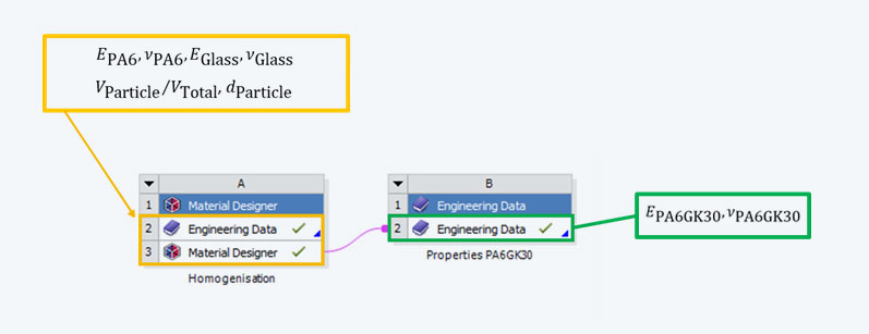
So, what remains to be done? For structural mechanics, the material behavior of the constituents, such as density, Young's modulus and Poisson's ratio, must be defined in the Engineering Data of the Material Designer. Of course, the relevant microstructure parameters have to be entered and then, after a few analysis settings, you can get started. When the calculations are complete, the Material Designer cell can be linked to the Engineering Data of a downstream analysis and the homogenized material can be used. The homogenized material can also be added to the database or exported as an xml file, so that homogenization only needs to be performed once per material!
For composites with statistical properties, there is one more important note: the RVE must be large with respect to the fibers or particles and contain many of them. In principle, one should make a study regarding the RVE size and choose it so large that the properties converge. This can be very expensive, since an RVE of double edge length has eight times as many elements and the computational cost increases disproportionately with the degrees of freedom. However, Material Designer offers a remedy: several RVEs can be analyzed for one parameter set and the results averaged. This effort increases only linearly and is therefore more efficient.
Example: particle reinforced plastic
Let's take a look at an example. We want to reinforce a matrix consisting of PA6 with glass particles, and the Young's modulus should double compared to the pure matrix. The big question is: how large must the particle fraction be? In the GRANTA Material Data for Simulation database, we find linear elastic properties: E_PA6= 1100 MPa, ʋ_PA6=0.35, and E_Glas= 7000 MPa, ʋ_Glas=0.21. For simplicity, we assume spherical particles with a uniform distribution of the diameter between 5 µm and 15 µm. The size of the RVE is 30 µm. As target values for particle volume fractions, 10%, 20% and 30% were analyzed, each with 3 RVEs per volume fraction.
The table below summarizes the results. It can be seen that the volume fraction is not exactly hit and the results show a scatter. However, given the RVE size, this was to be expected. These effects become smaller with larger RVEs. How are the results to be evaluated now? As an engineer, I have to say that it’s enough! Since it is impossible to order a material with a particle fraction of 27.3578 % anyway, and the input variables are also subject to fluctuation, this accuracy is completely sufficient. In this respect, 30% volume fraction would be suitable to double the Young's modulus of a composite material compared to the pure matrix, which would successfully solve this complex task with little effort.
| Particle fraction [%] | Effective Young´s Modulus [MPa] | Effektive Poisson´s ratio l [-] |
| 11,3 (±1,2) | 1416 (±27) | 0,33 (±0,01) |
| 22,4 (±2,9) | 1869 (±143) | 0,32 (±0,02) |
| 30,4 (±0,4) | 2246 (±60) | 0,31 (±0,01) |
Beyond elasticity - what's next?
Linear properties such as density, elastic and thermal properties are determined completely independently by the Material Designer. But what if we want to determine the effective plastic behavior with the simulation itself? Although the Material Designer also offers certain options for performing nonlinear analyses, we only gain full freedom when we switch to Ansys Mechanical. With a simple link on the project page, we can easily import the periodically meshed geometry of Material Designer into Ansys Mechanical. After the periodic boundary conditions have been applied, any load situation can be simulated with cycles, holding phases and load direction changes.
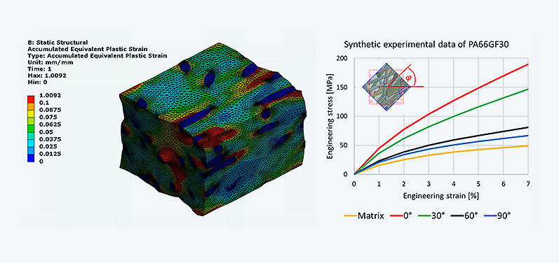
In the following example, the plastic material behavior of a short fiber reinforced composite is simulated. The polyamide matrix is modeled with plastic material and isotropic hardening, and the glass fibers are elastic. For anisotropic materials, tensile tests are readily performed in directions inclined to the fiber orientation. This can be done very conveniently in Ansys Mechanical via "Part Transform". The simulated stress-strain curves show a clear directional influence and can now be used to calibrate the Hill plasticity, just as if they had been measured in the experiment.
In summary, Ansys Material Designer represents a powerful digital materials laboratory. In conjunction with Ansys Mechanical, there are hardly any limits to the analysis of complex material properties that cannot be determined experimentally at all or only at great expense. In this respect, my appeal to you is: Try it yourself! Design the material that meets your needs on your own.
Author

Published: July 2023
Editorial
Dr.-Ing. Marold Moosrainer
Head of Professional Development
Cover images
Left: © CADFEM Germany GmbH
Right: © Adobe Stock


