Tech Article | 24/01
Screw loose? Quick dimensioning with Discovery!
They are practical, flexible, economical to implement, and we all know them: bolts. In this article, we will use a machine housing to demonstrate a workflow for bolt pre-design. The aim is to reduce the number of bolts required from the original 28 to a maximum of 12 due to a lack of space and high assembly effort.

The design of the bolt connection is not just a question of strength. In addition to the product design, it also has far-reaching effects on a number of aspects for the entire product life cycle. These include, for example, the structural performance of the joint, assembly, repair and maintenance costs or risks of material breakage, unwanted loosening, and energy loss due to vibrations.
This is why it is very valuable to be able to quickly and easily estimate the number, size, and position of the bolts required at an early stage of product development. We purposely refer to this as a "preliminary estimate" and not a "verification". The focus is on a qualitative statement that can be made quickly even by non-calculation specialists.
Screw simulation, isn't that time-consuming?
When it comes to dimensioning the bolts, matching the geometry can usually be achieved with manageable effort. However, bolt calculation can involve a great deal of effort. Many CAD systems provide the bolts in libraries, but they are often far too detailed, including thread, external hexagon and even the washer. This can be a major hurdle for traditional FEM simulation. In order to be able to simulate the model with an adequate amount of effort, a thorough defeaturing is necessary. If this is followed by material definition and meshing, this workflow quickly falls out of the "quick and easy" category.
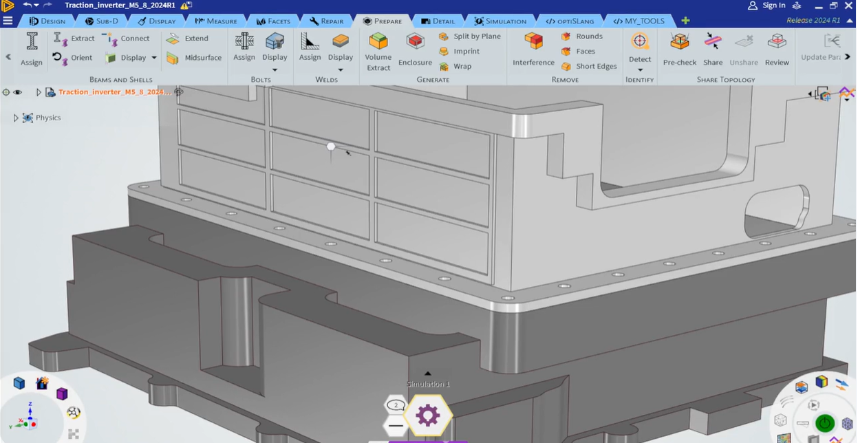
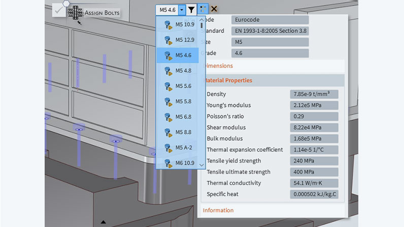
Ansys Discovery has implemented the "Assign Bolts" function. With "Assign Bolts", bolts and the associated holes are automatically identified with the push of a button. The system offers suitable bolt dimensions according to Eurocode, SAE and ASTM standards based on the diameter and hole depth. The bolts are listed according to size and strength class. This saves the user time-consuming geometry preparation and the need to search for suitable material and bolt data in tables.
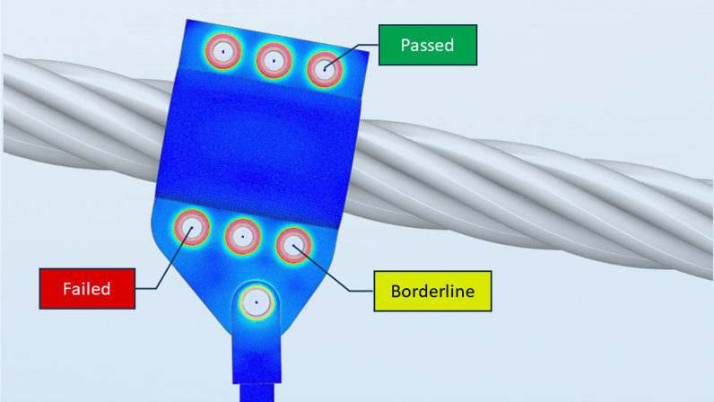
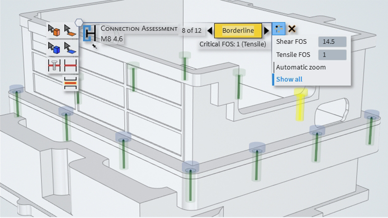
Once the selected bolt dimension is confirmed, the connecting components for the simulation are automatically created. This contains both the geometric bolts, which are discretized as beams (model class 2), as well as the material limit values according to the specific bolt dimension. After the simulation has been carried out, all bolts are evaluated in an automated process. For a quick overview, each bolt is displayed in color based on the Factor of Safety for tensile strength and shear strength. The exact values for the Factors of Safety can also be displayed for each bolt or exported as an entire table.
Screws and contacts - a scary topic? No!
Experience shows that a bolt rarely comes alone. There are usually several, sometimes several hundred. Accordingly, the time required to define the contacts for the simulation model is not insignificant. The contacts on the bolt head, the bolt shank and the thread must be both created and adjusted, in the worst cases even for each individual bolt. The Ansys Discovery workflow presented here with the "Assign Bolts" function addresses this point and completely takes over the task of defining the bolt contacts.
The contact between the bolt head and the flange as well as between the thread and the hole is automatically modeled with MPC bonded contacts. This keeps the bolt head from sliding under load and also prevents the thread from loosening. The housing halves can be connected to each other using a frictional contact. These are common criteria for simple applications. As mentioned above, this workflow is a preliminary design and not a verification. With these contact settings, a quick and robust simulation can be ensured for most tasks without the challenges associated with meshing and convergence.
Resizing screws - step by step
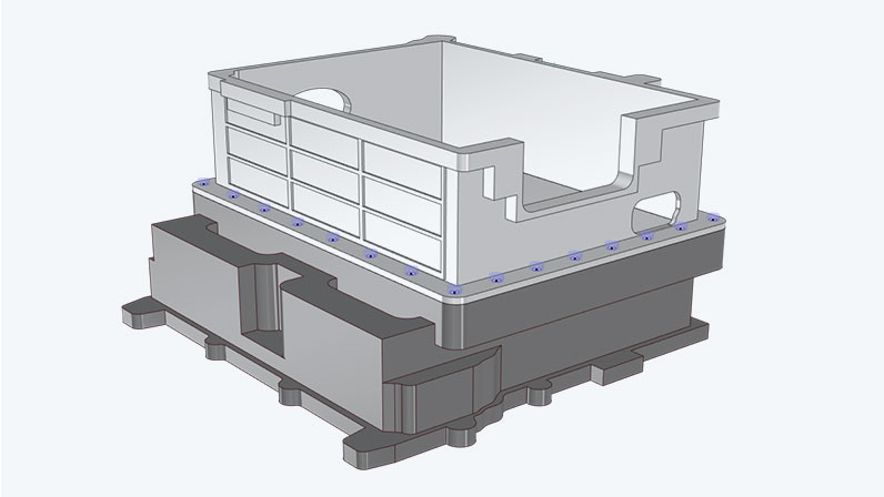
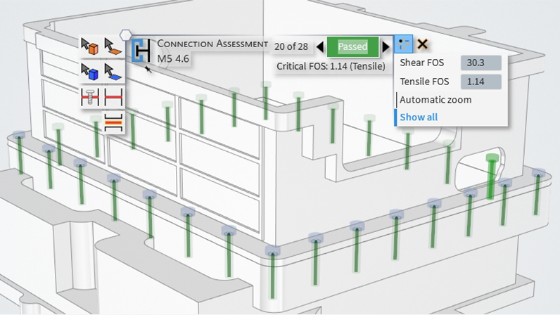
In this representative example, a housing bolt connection is analyzed and dimensioned. Initially, 28 M5 bolts with strength class 4.6 are provided for the model with the prescribed loads. There are 8 bolts on each side with common corner bolts. The task is to reduce the number of bolts due to tight mounting conditions. A maximum of 4 bolts may be used on each side. A reliable and secure connection must be ensured. The bolt dimension should not exceed M8. All bolts are preloaded with the respective permissible bolt preloads according to DIN 912.
The model under consideration consists of two machine housing halves made of steel. The lower segment is subjected to internal oil pressure. There are additional structures on the upper segment. The load of these structures, due to their dead load, is applied using a point mass at the center of gravity to the upper connecting surface with the acceleration of gravity. The simulation represents the operating load case in the worst-case scenario.
The evaluation of the initial model in Discovery results in a minimum Factor of Safety for the tensile strength of 1.14. This means that there is sufficient safety for the load under consideration. However, the Factor of Safety is only slightly greater than 1. It can be assumed that the Factor of Safety will fall below 1 by reducing the number of bolts. We would like to perform a systematic check of the bolt dimensions with 4 bolts per side. Although we can assume from the results of the initial condition that a bolt dimension of M5-4.6 will not be sufficient, we want to start from the bottom and work our way up to the required minimum bolt dimension.
Fewer screws, more space
If the geometry model is set up parametrically, for example with the History Tracking feature in Discovery or in an external CAD system, the number of bolts and the dimension can be quickly adjusted. The model of the housing bolt connection is fully parameterized in Discovery and can therefore be modified very quickly.
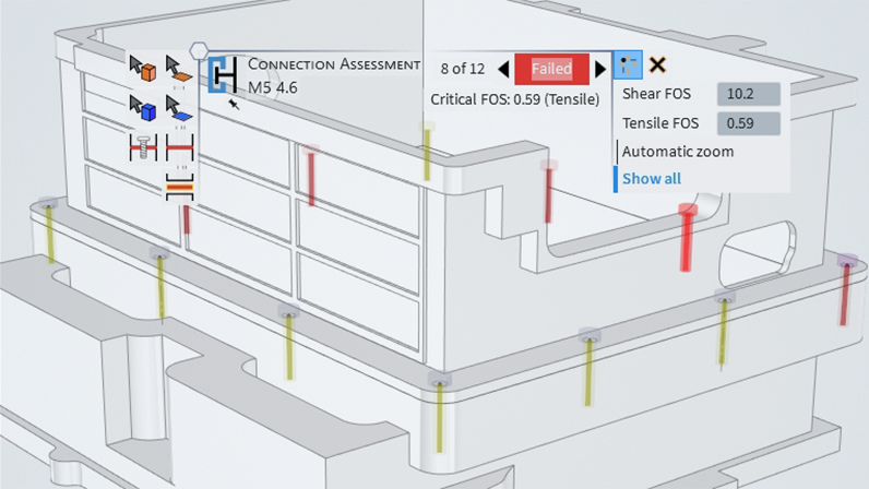
The result of the bolt assessment for the adapted variant with 4 M5-4.6 bolts on each side shows that the Factor of Safety for the tensile strength falls well below 1 for 5 out of 12 bolts. For the remaining bolts, this value is between 0.91 and 1.08, and thus in the limit range. For the next variant, the larger M6-4.6 bolt dimension is used.
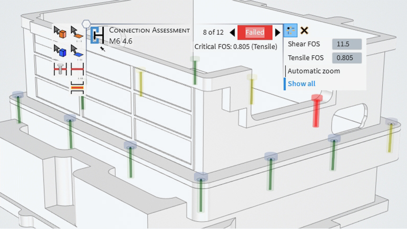
Even after the bolt dimension in the geometry model was adjusted to M6-4.6, the evaluation showed a Factor of Safety for the tensile strength of 0.784 for a bolt and thus still clearly < 1. For another 4 bolts, this value is still in the limit range between 0.91 and 1.07.
Better not to design too scarcely
For the next larger bolt dimension of M8-4.6, the Factor of Safety for tensile strength is between 1.0 and 1.77, which means that no bolt is below 1. However, one bolt is in the limit range. By using M8 bolts, the defined maximum permissible bolt dimension for this task is achieved. An additional increase in the Factors of Safety can be achieved by matching the strength class, for example from 4.6 to 5.6.
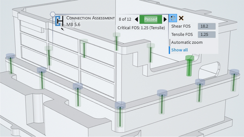
The strength class can be changed with the push of a button using the "Assign Bolts" function. Since this is not a geometric change, the simulation does not necessarily have to be carried out again unless the bolt preload changes. However, this is not the case in our model. An update of the bolt evaluation is sufficient. The Factor of Safety of the tensile strength has increased and is now between 1.25 and 1.86 with a comfortable buffer.
The knowledge in this example is not only limited to the numerical values of the Factors of Safety. The gain in know-how is just as valuable. The user quickly learns and understands the correlations in which areas the bolts are subjected to higher loads than in other areas as well as what additional reliability a change in the dimensions or number of bolts can provide. Furthermore, this workflow could also be used to analyze an uneven arrangement of bolts including the targeted positioning of bolts where they are needed. Optimizing bolt positions would be a suitable and relevant topic for future articles.
Next step: Evaluation according to specific regulations
Ansys Discovery takes advantage of the integrated Eurocode 3 database in combination with powerful modeling functions and proven Ansys solvers. The "Assign Bolts" function makes it possible for any engineer to quickly realize the preliminary design. When it comes to the verification of bolt connections later in the development process, there are two different guidelines, Eurocode 3 and VDI 2230, which deal with this topic.
Eurocode 3 is a European guideline for steel construction, while VDI 2230 "Systematic calculation of highly stressed bolt connections" is a guideline of the Association of German Engineers (VDI) that deals with the calculation of bolt connections in mechanical engineering. Eurocode 3 offers comprehensive coverage for various applications in steel construction. The advantage of this guideline is that little information is required to make reliable statements. However, VDI 2230 is much different. It is specifically geared towards bolt connections in mechanical engineering and is generally much more detailed.
Does this topic resonate with you? Then take a look at the trainings linked below. The courses ranges from preliminary design with Discovery to verification in Mechanical with the "Bolt Assessment inside ANSYS" tool. And if you are not sure which training is best suited to your tasks, please contact us. We will find a solution together.
Author

Published: January 2024
Editor
Dr.-Ing. Marold Moosrainer
Head of Professional Development
Cover images:
Left: © CADFEM Germany GmbH
Right: © Adobe Stock


