Tech Article | 24/02
Process integration of CAE workflows in optiSLang
Process integration deals with coordinating processes and analyzing interfaces. If you search for the term on the internet, you will mainly find hits relating to manufacturing and logistics. But is this topic also relevant to digital engineering? YOU BET! There are many interfaces involved here too – not only between people, but also in the tools used.

Simulation processes in product development
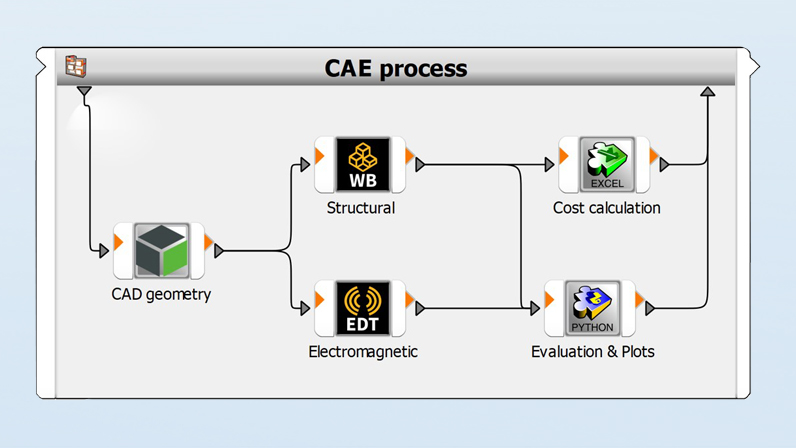
“We don’t follow a strict process for simulation!” “We do it based on experience.” “We’ve always done it this way!” If these statements ring true to you, then we need to take a step back. You rarely start a simulation from scratch, do you? We usually receive a CAD geometry from a designer, for example, which is first prepared for the simulation task. Only then do we turn our attention to material data, meshing, contacts, and analysis settings in the pre-processor. After solving, the results are evaluated in post-processing. Additional software such as Excel, Python, or MATLAB is often used to create further evaluations, special plots, or verifications.
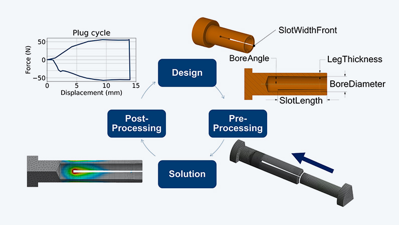
Such a process, as shown in the figure below, is typically iterative; findings from the simulation results are in turn incorporated into the product. In particular, if the CAE process is characterized by manual steps and if several people are involved, the risk of losing the overview increases with each iteration. If the CAD data is transferred again and again by the designer, different versions accumulate on the hard disk (v2, v3, ..., final, final2, ...). You may have a routine for adapting the model, but careless mistakes happen quickly. Are the results then still comparable? And how do you proceed systematically with the iterations so as not to poke around in the dark?
This raises the question of how we can establish a robust process. In this article, we look at the simulation process of a plug connector as an example. As input, we need a geometry model that is adapted during the iterations. The mechanical behavior of plugging and unplugging is evaluated to determine the required forces and life cycle. An electromagnetic analysis of the signal and power integrity is also of interest. How do the findings from both areas contribute to a targeted approach in the iterations? And what about the costs? If this is only considered once development is complete, are we starting from scratch?
Automation = programming?
Interfaces are the basis for linked processes. In the CAE environment, these are partially integrated into the software tools. The modeling tool, for example, often supports the import of common CAD formats. For evaluations in Excel, we can often get by with copy-paste and manual work. However, for colleagues who use different simulation tools, each result has to be explained separately. The aim of process integration is to combine models from different tools – even if there is no interface – in a graphical user interface to form a tool chain; ideally without writing a single line of code!
A process chain, which is explained in more detail in the next section, puts our tools in the right order and reflects the engineering process. However, it does not relieve us of the manual steps in the models. So, if you are aiming for a continuous process, you should think about how a certain degree of automation can be achieved in the models. Does automation here mean that programming is inevitable? This can clearly be answered in the negative, as virtually all CAE tools can be parameterized!
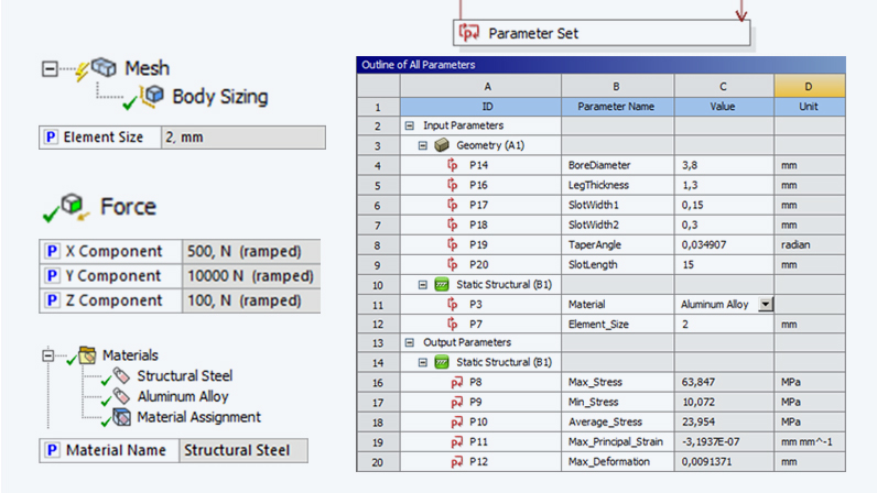
Ansys Mechanical, for example, offers very simple parameterization. There is a small checkbox next to most of the input fields. When you click on it, a small “P” appears, as indicated in the picture below. This allows you to quickly control material data, mesh settings, boundary conditions and much more using parameters. Did you know that not only can material parameters be parameterized, but also the material assigned to components using the Material Assignment? When the Mechanical analysis is created within Ansys Workbench, the parameters appear in the “Parameter Set” together with all parameters from an integrated CAD model or other analyses.
A process cannot be replicated in Workbench?
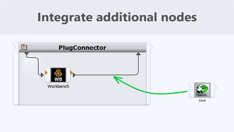
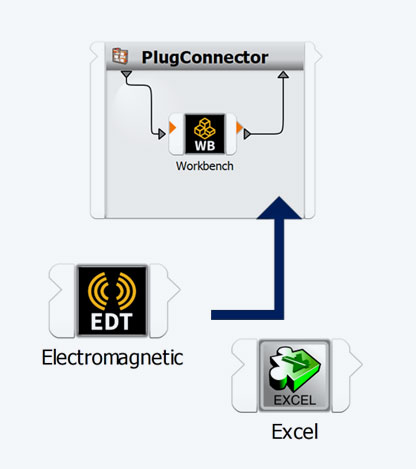
The Workbench is a simulation platform that offers CAD interfaces, multiphysics analyses, parameterization, and much more. But what if your process cannot be fully replicated with it? For example, the structural-mechanical model of the connector is built with the Workbench, while the colleague uses Electronics Desktop for the electromagnetics. And what about plots that are created with Python? This is where a process integration tool such as optiSLang comes into play. As you can see in the illustration, we use specialized nodes to control various tools. These connectors can be arranged and connected in the graphical user interface to create a workflow.
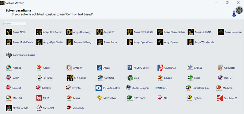
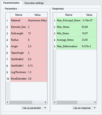
The first step is to integrate the parameterized models into optiSLang. To do this, the “Solver Wizard” can be used to connect Ansys solvers or tools from other manufacturers – regardless of whether the models are simple or complex, from structural or fluid mechanics, electromagnetics, or optics. After selecting the Workbench project with the connector, all input (red) and output parameters (green) are identified. The parameters are then managed in optiSLang, where upper and lower limit values are defined, as well as material names for the parameter from the material assignment, for example.
Keep an eye on product costs with optiSLang
If a workflow is to be created from individual nodes, the tools must of course be connected. In our example, we would like to carry out an initial cost estimate in Excel based on the CAD parameters. The spreadsheet is fed with geometric dimensions for each variant in order to determine the costs. As there is also an interface for this tool in optiSLang, the Excel node can be dragged directly onto the connection as shown in the video. Cells are defined as input and output in the node. If the parameter names of an optiSLang node match those of another node, the values are directly linked.
Other models are integrated into the workflow in the same way. For example, nodes for the Electronics Desktop model or a Python plot are added. You decide in which order the nodes are placed and thereby executed. While independent simulations can run simultaneously, post-processing can only be carried out afterwards. If the process chain is started, the Excel calculation always runs after the simulations. Even though the focus is on mechanical performance, we have also generated other results such as costs or signal integrity for each variant. By keeping an eye on costs, you can avoid expensive mistakes!
Efficiently compare variants and identify trends
So far, we have focused on the inputs and the process, but what about the results? When you calculate many variants one after the other, you can quickly accumulate a lot of files. Do you still know which geometry version “Model_V3_final_2” belongs to? And isn't there a subfolder with additional results? If there are no notes on individual variants, there is no way around reopening the models. We also need to merge this with the results of our colleague from the Electronics Desktop, but which variants fit together? Process integration keeps us from comparing apples to oranges.
optiSLang thinks in terms of design points, i.e. a unique combination of values for the input parameters. Analogous to the scalar inputs, the output parameters – such as the maximum stress, the required insertion force, and the costs – are available for evaluation. For each new design variant, a folder is created within the working directory where all result files are saved. It is up to you to decide whether to keep the entire model or just individual text or image files. In addition, results from subsequent nodes, such as an evaluation script, can be imported and used again. But don't worry, you won't have to search for the files manually.
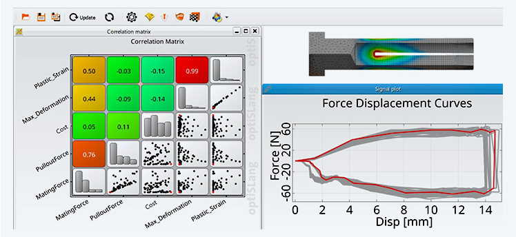
Variants are compared in optiSLang post-processing, which offers a wide range of visualizations. Scalar results such as forces, stresses, costs, etc. can be compared for the connector. This allows us to identify trends such as a linear relationship between strain and deformation at first glance. Additionally, calculated signals such as force-displacement curves, frequency spectra, or S-parameters can be displayed. In addition to the curves of the insertion and removal process, generated plots can be integrated from the design folders. The display is interactive and updates automatically according to the selection of the design point. Comparing has never been so easy!
Understanding designs with a sensitivity analysis
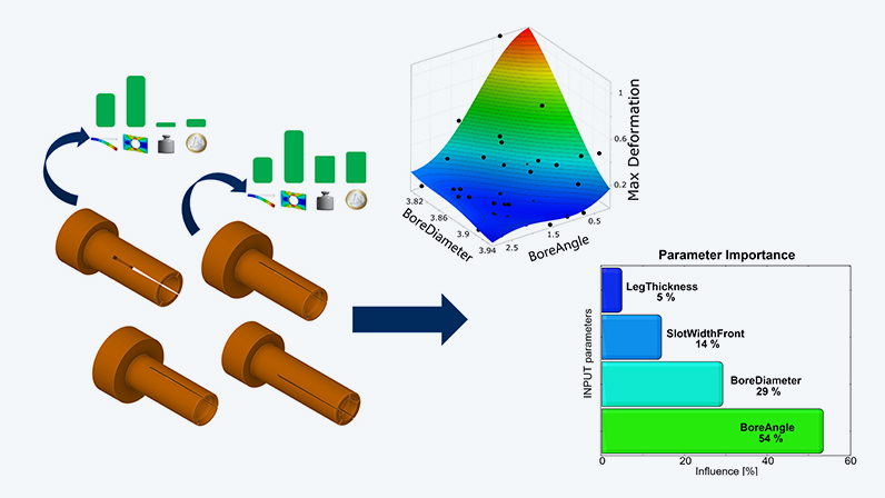
Process integration is not only suitable for automating CAE workflows, but it also paves the way for parametric studies. With a sensitivity analysis in optiSLang, a variation space that is spanned by the parameters is systematically scanned. You then do not have to specify individual variants, but only the parameter limits. Response surfaces are generated from a sampling in order to determine and trace correlations between the design variations and the varying result parameters. This enables the identification of relevant parameters across all included models - regardless of the node from which the results originate. Let’s start with these connector parameters:
| Parameter name | Parameter limits | |||||
| BoreDiameter: | 3,7 - 3,95mm | |||||
| BoreAngles | 0,1° - 3° | |||||
| LegThickness | 0,5 - 2mm | |||||
| SlotLength: | 13,5 - 15mm | |||||
| SlotWidthFront: | 0,1 - 0,3mm | |||||
Variation range of the plug connector parameters
For the plug connector, this means that even non-linear relationships such as maximum deformation can be explained. Not all inputs influence this result equally. Instead, only some, such as the bore diameter and the bore angle, play a major role. In contrast, the length of the slot does not have a major influence on any output parameter. For this reason, the slot length is filtered out and the previous reference value of 14 mm is used. In addition, a statement can be made as to whether the desired product properties such as the specified insertion forces are feasible at the target costs within the analyzed range.
Design Optimization with optiSLang
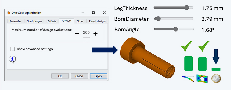
After a sensitivity analysis, we understand the correlations in our design and which parameters are relevant for our target values. Negligible parameters have already been filtered out. But how are the remaining parameters adjusted so that we can find an optimal design? This can be achieved by optimization - a piece of cake with the process chain and the parameters! But isn’t this all complicated? No, because with the One-Click-Optimizer, all you need is your objective and the number of designs you can afford to calculate!
Various objectives can thus be addressed for the connector – even if they conflict with each other. The forces required to connect and disconnect the connector should meet the customer’s requirements, while also keeping manufacturing costs as low as possible. At the same time, the limits for stresses or plastic strains must not be exceeded. In addition to the target functions, conditions such as a permissible stress are defined (σ < 50 MPa). The optimizer then approaches the solution iteratively until an optimum parameter combination is found. And the best thing about it is that, if the requirements change, we simply run the optimization again with the workflow and adjusted objectives.
Your first automated simulation process?
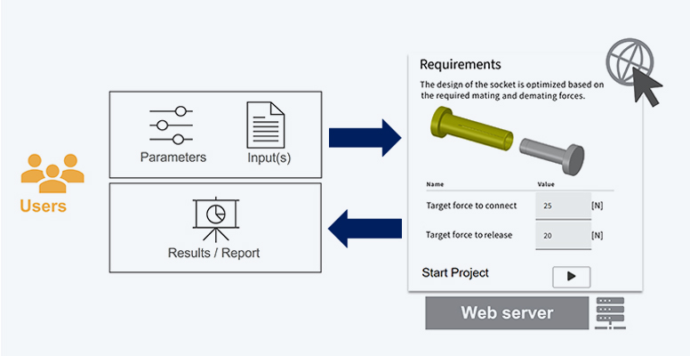
The process chains created are not only suitable for calculating variants or systematically carrying out parameter studies, but also for making the simulation process available to a wider range of users. The idea behind this is simple. The creator of the workflow decides which parameters and settings are made available to users. The users, who do not require simulation expertise, then fill in a simple input mask via the web browser and start the workflow on a server. Particularly for recurring simulation tasks, you as a simulation expert are relieved of standard tasks, which drastically reduces the waiting time for simulation results!
Perhaps you don’t connect plugs like those used in our example, but will you connect your processes in the future? You will certainly encounter some of the challenges described in this article in the development process. However, you don’t have to settle for the “we’ve always done it this way” approach. Instead, take advantage of the potential of automated simulation workflows and systematic parameter studies. Get started in the world of process integration and design optimization with the link to the optiSLang training. Not yet sure whether your workflow can be replicated as a process chain? Or whether a web application is suitable for you? Then get in touch with us. We will find a solution together with you.
Author

Published: January 2024
Editor
Malte Küper
Berechnungsingenieur
Cover images:
Left: © CADFEM GmbH
Right: © Adobe Stock


