Tech Article | 23/06
Saving CO2 with Ansys Topology Optimization
It's getting serious: CO2 reduction is at the center of politics and is essential for the survival of society and companies alike. Minimizing component mass leads to lower energy and material consumption in production and operation, thus achieving a twofold benefit. In this article, we use the topology optimization of an engine mount to show how you can save mass in a targeted manner.


Goal: less CO2 - How: save material
We all know that major efforts are needed to reduce CO2 emissions worldwide. But what are the options for doing so in the transportation sector? Due to a lack of alternatives and long development cycles, it will not be possible to get by without fossil fuels in the foreseeable future, especially in aviation. One way to save CO2 is to reduce the overall mass. This, in turn, means that each individual component must be weight-optimized. Reduced mass means double savings: less material is needed in production and less fuel is burned in operation.
Not every component immediately shows whether and, above all, where excess material can be saved. Each component has areas of high and areas of low strain energy, depending on the load. Heavily loaded areas form the load paths and are essential for the function of the component and these must be retained. Areas of low strain energy, on the other hand, are unimportant and can be omitted to save weight. The ultimate question is how can the relevant areas be identified? Through experience and gut feeling, a good designer will be able to find a suitable design. However, is this design really optimal? How can an inexperienced engineer approach this task?
Regardless of whether an existing component is to be optimized or a start is to be made from a blank sheet of paper, topology optimization is a true idea machine for everyone. Here, one iteratively approaches an optimal material distribution for the component. For example, a low mass, maximum stiffness, or minimum stresses can be defined as optimization goals. With constraints, the resulting shape can even be influenced with respect to various manufacturing processes.

Topology optimization – how does it work?
Topology optimization is only one of the many disciplines of structural optimization (in addition to shape, topography, and lattice optimization). It is based on the fact that, starting from a predefined design space (a maximum possible initial volume), material is gradually removed or redistributed in accordance with the load paths. Ultimately, a coherent topology is created. Areas that should be preserved, where boundary conditions and loads are introduced, are defined as exclusions, and are excluded during optimization.
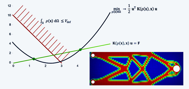
How do you define where material must be preserved and where material can be saved? There are two approaches to this in Ansys Mechanical: the SIMP (Solid Isotropic Material with Penalization) approach, in which the so-called pseudo-density is introduced as a parameter. Each FE element is given an additional status of being more or less contained in the component (rho = 0: can be removed, rho = 1: material remains). The level set method, on the other hand, does not require a parameter. The surface of the structure is described by a function. This changes from the initial installation space to an optimal structure. Several non-connected sub-areas of the topology can be formed.
As with any optimization task, an objective function is required to describe the optimization goal. A standard task is to maximize the stiffness of a structure. This point would correspond to the smallest function value of the blue curve. However, it does not necessarily satisfy the criteria of a real optimal structure. A fully filled structure is of course the stiffest of all solutions but not a solution of the problem. For this, additional equality and inequality constraints, so-called restrictions (red curve), have to be introduced. For example, the mass could be reduced to a fixed value, or the stresses must not exceed a certain limit.

And what about in the software?
A requirement for any topology optimization is a preliminary basic analysis (e.g. static analysis, modal analysis, thermal analysis in system A). The geometry of the basic analysis contains the component with the maximum possible optimization region. All loads and boundary conditions that occur must be included. This is because the optimization result is only optimal for the load scenarios that have been defined. Any change of loads and boundary conditions or any missing load can lead to changed optimization results. As it is known from other coupled systems, a Structural Optimization system is linked to the basic analysis.
The collective term Structural Optimization covers various optimization approaches (more on this later), including topology optimization using the SIMP approach as default. Load introduction points and boundary conditions are automatically defined as exclusion regions. The objective function has to be specified, e.g. minimization of mass, and the restrictions have to be defined. The influence of individual load steps or natural frequencies of the basic analysis can be weighted differently. Deformation and stress results can be displayed directly on the optimized structure. This structure is available as an STL body and can be exported.
In order to validate the results, it is recommended to perform a validation calculation based on the reconstructed CAD geometry in the next step. The validation system is created as a copy of the base system. However, the initial geometry is replaced by the optimized geometry, which is usually still fed back to a CAD geometry in cell C3. Deformation and stress results of the validation system can be directly compared with the base analysis.

Example: aircraft engine mounting
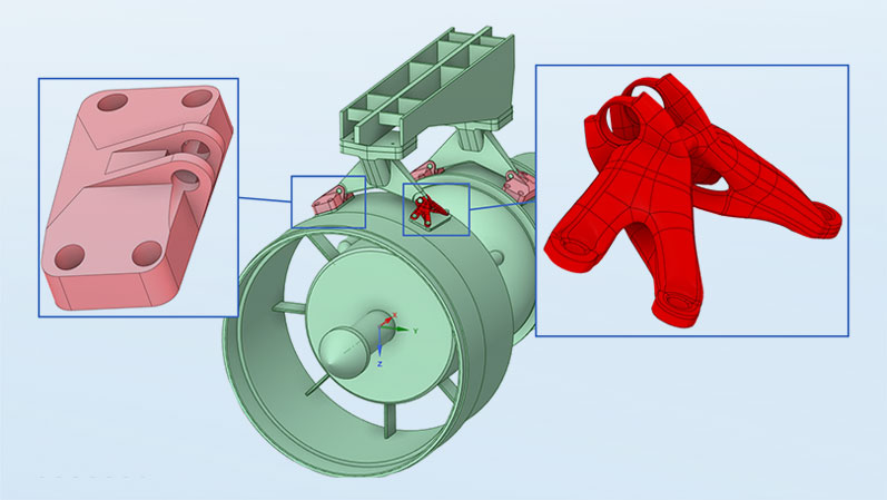
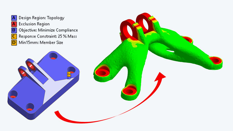
Let's look at the specific case of the mounting of an aircraft engine. The component is fixed at four bolted points. Forces and moments are applied to the bolt bearing in several load steps of the basic analysis. An aluminum alloy is assumed as the material. Again, the objective function is to maximize stiffness. The mass is to be reduced to 25% of the initial component (maximum design space). The dimensions of the members that may arise are limited by a minimum value of 15 mm, so that the structures are not too delicate. Other possible restrictions include displacements, reaction forces, global stresses.
In this case, the goal of a 75% reduction in mass compared to the initial build envelope was achieved. According to Ansys Granta Selector, this corresponds to a saving of 16 kg CO2 per component for the 6061 alloy - not including savings during operation. 16 kg CO2 doesn't sound like much, but it makes all the difference in quantities of thousands or even millions. To put it in perspective: compared to a fixture designed based on experience, you certainly don't save 75%, but maybe it's 15%, which is still quite a lot. And best of all, this method can be used by anyone, no matter how many mounts they have constructed in their lifetime!
But can this structure also be manufactured and, if so, with which processes? Additive manufacturing would be an obvious option here, but beyond that, you would be limited in the choice of manufacturing process. Therefore, manufacturing constraints now come into play. If it is known from the outset that the component should be manufactured using a casting process, the demolding directions of the mold can be defined as a constraint and a castable structure would be formed. In addition, other manufacturing constraints exist, which would lead, for example, to an extrudable structure or a waterproof structure similar to a housing.

Back to CAD: Geometry reconstruction
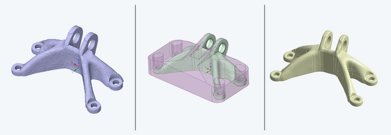
However, the optimization result is only half the battle. The optimized structure is available as an STL body and can be exported as such. For further use, however, the structure must ideally be converted back into a CAD geometry. Ansys Discovery provides the necessary tools for this. By means of shrink-wrapping, the tessellated STL surface can be covered with a smoother surface. The decisive factor here is a sufficiently small, but not too small, value for the new triangular surfaces to be generated.
The subsequent smoothing refines the surface. The "Flatten Peaks" option with a limiting angle of 360° rounds the structure to such an extent that the Auto Skin function can use it to generate closed free-form surfaces at the push of a button, thus creating CAD geometry again. Areas previously cleverly cut out of the initial geometry and reintegrated can help generate cleanly designed surfaces for loads and boundary conditions. This closes the circle, and we can continue with a weight-optimized component in the development process.

Is that all there is to it?
As already mentioned, topology optimization is only one part of structure optimization. If the topology of the structure is to remain basically unchanged, but the surfaces are to be optimized, the options available are shape optimization for volume components and topography optimization for shell structures. Here, using a mesh morphing algorithm, the surface nodes are moved in such a way as to produce the stiffest possible surface or a surface with the lowest possible stress. Particularly stiff sheet metal components can be produced by optimally arranged stiffeners and beads.
If the outer appearance of a component should not be fundamentally changed, it is possible to provide an internal lattice structure instead of solid material. Various lattice patterns can be selected. The diameters of the lattice members are adapted to the load situation. In the area of the load paths, thicker members are provided. These structures can then only be manufactured additively, which brings us to the next step in the product development process.
Of course, the manufacturing process of an additively manufactured metal component can also be simulated, regardless of whether a powder bed or sintering process is used. The software helps to identify critical areas even before printing. In addition, the distortion compensation provides a preformed component in such a way that an almost undeformed end result can be achieved during printing. Simulation thus helps to avoid costly misprints. The combination of structural optimization and process simulation thus produces innovative and efficient components. Try it yourself and break new ground in the design process!

Author

Published: October 2023
Editorial
Dr.-Ing. Marold Moosrainer
Head of Professional Development
Cover Images:
Right: © Adobe Stock
Left: © CADFEM Germany GmbH


