Tech Article | 24/04
Stiffness Boost Thanks to Composite Simulation
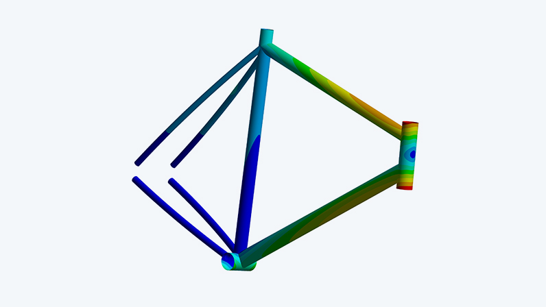
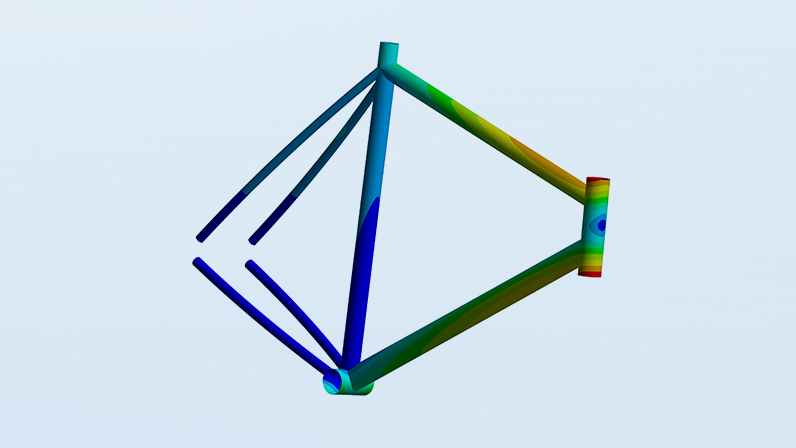
To achieve top performance in road cycling, the focus is increasingly on the perfect frame - lightweight, stiff, and aerodynamic. Learn in this article how Ansys ACP can assist engineers in optimizing the head tube stiffness of composite bicycle frames, enabling a weight reduction of 30% compared to aluminum frames.

Carbon Fiber Lightness for Optimal Road Bike Frames
To optimally tackle the technological challenges of today, lightweight construction plays a crucial role. This is exemplified by the increased efficiency of airplanes, or on a smaller scale, maximizing personal achievements on a road bike. Whether a professional athlete or a hobby cyclist, who wouldn't want to save crucial seconds during challenging mountain stages? In addition to essential rigorous training, a weight-optimized road bike frame can provide significant benefits. Efficient pedaling and agile maneuvering in curves not only require a reduction in weight but also a specific stiffness of the frame.
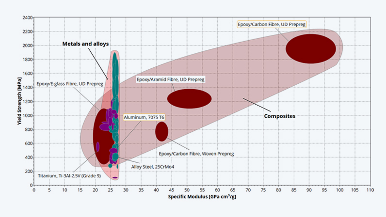
For performance road bike frames, essentially two materials are considered. Aluminum is taken into account due to its acceptable weight-to-stiffness ratio and its good design and manufacturability. However, it is surpassed by carbon fiber reinforced plastic (CFRP) for several reasons. The attached Ashby diagram from Ansys Granta Selector highlights the superior strength and excellent specific stiffness as significant advantages when compared to various lightweight materials. While aluminum is easier to manufacture, CFRP, by contrast, allows for precise adjustments of stiffness in local areas due to the fiber structure, making it more versatile.
In this article, a composite bicycle frame is specifically optimized for its head tube stiffness. Since manual calculations would be impossible in this case, Ansys tools are utilized, which assist engineers in handling the complexity of a layer setup and its determination. With the help of Ansys Composite PrePost (ACP), a manufacturing-oriented laminate is defined, which is then analyzed in Ansys Mechanical for its deformation behavior. Based on this, a parameter study is conducted to determine the optimal number of layers in 0°, 45°, and 90° directions, resulting in a 30% weight saving compared to aluminum.
Composite Stiffness: From Single Ply to Laminate
The fiber-reinforced plastics used in bicycle frame construction fundamentally consist of a composite of epoxy resin as the matrix and carbon fibers for the decisive stiffness and strength. These composite materials exhibit orthotropic material behavior, meaning they possess significantly higher mechanical properties in the fiber direction compared to directions perpendicular to the fiber orientation. To optimally utilize this characteristic and to ensure maximum stiffness, unidirectional (UD) layers are used, which orient the fibers exclusively in one direction.
In various areas of the frame, the orientation of UD layers can be flexibly adjusted to the respective loads. A 0° layer along the tube axis strengthens the bending stiffness and supports the laminate under tensile and compressive stresses. An orientation at 45° to the main direction counteracts shear stresses, while a 90° layer improves resistance against the collapse of the cross-section. Depending on the stress, the orientations of the layers and their number in the frame sections can vary, creating a flexible layer structure that significantly influences the mechanical properties.
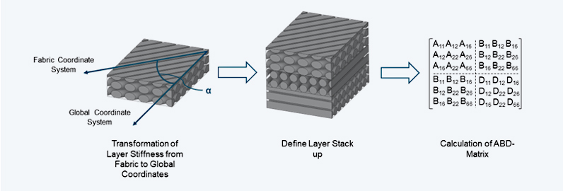
The stiffness of a planar multi-layer composite can still be manually calculated. The stiffness of individual layers is transferred based on the fiber orientation into a global coordinate system. Afterward, using classical laminate theory, the so-called ABD matrix can be determined to describe the elastic behavior of the laminate. It consists of three submatrices, where the A matrix represents the in-plane stiffness. The D entries describe the resistance to bending or the plate stiffness, and the coupling stiffness matrix B provides information on whether there are couplings between in-plane and bending properties, such as shear as a result of bending, within the laminate.
How do I define a composite in Ansys?
The manual derivation of the stiffness characteristics of a laminate and their subsequent implementation via APDL into an FE calculation is, in principle, feasible – but honestly, for complex models like a bicycle frame, this would be an incredibly tedious endeavor. A far more efficient and user-friendly solution is offered by the software add-on Ansys Composite PrePost (ACP), integrated into the Workbench. This tool not only determines the mechanical properties of the laminate but also allows for the analysis of manufacturing-relevant effects, such as draping effects on highly curved surfaces.
The workflow begins with the creation of a shell mesh using the proven Ansys Mechanical features. Furthermore, the grouping of surfaces for possible individual layer definitions can be carried out using "Named Selections". Within ACP itself, all laminate-specific definitions are established. The range of possibilities extends from the definition of a "Fabric", which represents the used textile, through "Rosettes", which provide a solution if the fibers must follow a complex guideline, to "Oriented Selection Sets" for defining different laminate zones. Finally, the layers themselves are defined and structured under "Modeling Plies".
After defining the laminate and checking the manufacturing parameters in ACP, as shown in the video, a straightforward connection with a simulation block is made through simple drag-and-drop within the Workbench. In addition to a conventional static calculation in Ansys Mechanical, the coupling also enables, among other things, a transfer to an explicit analysis in LS-DYNA. The connection of ACP with a simulation block results in the transfer of the laminate properties to the shell mesh of the analysis. After defining the simulation boundary conditions, the simulation model can be analyzed in the usual manner.
Head Tube Stiffness: Layer Configuration via Parametric Study
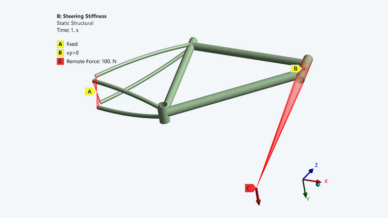
Following this general overview, the insights gained are applied to the road bike frame model. Traditionally, the analysis of head tube stiffness is conducted through prototypes, but these are often too costly and time-consuming. For the simulation, the following boundary conditions are derived from the standardized test: The surfaces of the dropouts at the rear are fixed in all 6 spatial directions using a "Remote Displacement". Additionally, movement of the steerer tube center in the y-direction is suppressed, while a load of 100 N is applied through a "Remote Force" at a distance of 1000 mm at the ends of the steerer tube.
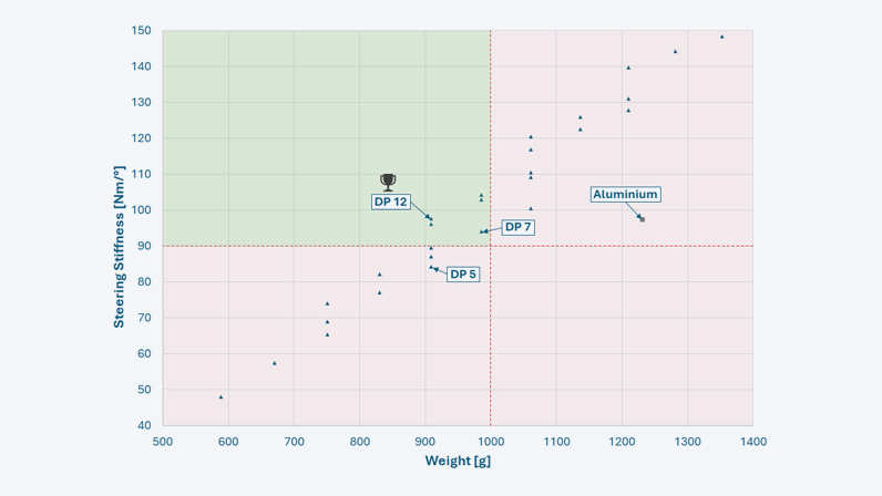
To narrow down the result space in the layer configuration design, clear design goals are essential. For the road bike frame, therefore, a minimum head tube stiffness of 90 Nm/° with a maximum weight of 1000 g is the stated goal. The stiffness is calculated based on the twisting around the center of the steerer tube and the torque resulting from the load, which corresponds to 100 Nm at this point. Thus, in addition to the simulation boundary conditions, the optimization goals of the subsequent parametric study are known, and only the layer configuration remains to be determined.
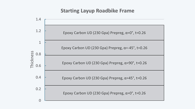
But how do you define a laminate when there are no prior experiences to draw from? A recommended starting point is the definition of a laminate with a symmetrical and balanced layer configuration. This minimizes coupling of loads and internal shear stresses between the layers. For the preliminary analysis of the frame in ACP, 5 layers of UD (unidirectional) fabric are chosen, with the orientation set at [0°/+45°/90°/-45°/0°]. The mid-plane of the laminate is at the 90° layer. As optimization parameters, the number of individual layers is defined, with the parameter space limited to 1 to 3 layers per orientation. An additional symmetry condition thus results in 27 different design variants.
Ideal Layer Definition and Further Insights
Using the integrated parameter set in the Workbench, the 27 design variants can be quickly generated, and the desired deformation values can be calculated in under 20 minutes. The evaluation is based on the diagram shown below. Only 5 design variants are located in the upper left quadrant (highlighted in green) and thus meet the requirement of 90 Nm/° head tube stiffness at a maximum weight of 1000 g. The variant DP12 shows the best ratio of stiffness to weight, with 97.58 Nm/° at only 908 g. In the parameter set, this variant's layer configuration is shown as [2x0°/2x+45°/90°/2x-45°/2x0°], totaling 9 layers.
The success of the layer configuration becomes evident when compared with an equivalent aluminum frame: The latter would have over 30% more weight at the same stiffness! The designs DP5 and DP7 from the diagram show additional remarkable insights. Despite having the same or even higher number of layers – as is the case with DP7 – they exhibit lower head tube stiffness. These comparisons underline the importance of fiber orientation in relation to the load. While some of these aspects might be intuitively understood with experience, simulation with the help of Ansys ACP opens up an endless expansion of possibilities with minimal time investment.
Is variant DP12 the layer configuration to proceed with into manufacturing? Short and concise answer: No. The preliminary design provides a very good indication, but it must be considered that it was limited to one load case and ignored other criteria such as bottom bracket or rear triangle stiffness. A symmetry of the laminate of 〖["2x0°/+45°/-45°/" ("90°" ) ̅]〗_S would additionally bring an improvement. The same layer configuration across the entire frame represents another idealization. Ideally, the individual parts of the frame would have different layer configurations. These and other possible improvements can be included in the simulation.
The Extra Mile: What Else is Possible?
Analyzing the stiffness of composite components only covers half the ground. A comprehensive evaluation additionally requires the assessment of composite-specific failure criteria. Through the laminate definition in Ansys ACP, criteria according to Puck, Tsai-Wu, Hashin, and others, as well as sandwich criteria, for example, can be evaluated in Mechanical. Furthermore, the analysis allows for the assessment of the most stressed ply and the progression of the reserve factor across the laminate thickness.
Shell meshing reaches its limits when normal stresses in the thickness direction cannot be neglected, as can occur with impact loads on the rear assembly of a bicycle, for example. ACP allows for the discretization of the laminate with solid or special solid-shell elements to meet these challenges. Although ACP can evaluate interlaminar shear stresses of a shell model due to its specialized approach, solid modeling offers advantages for a more precise analysis. Subsequently, the selection of damage models such as First Ply Failure or Progressive Ply Failure is flexible.
Not enough? If you would like to discuss further possibilities of composite analysis in ACP, such as automation through Python or integration with Ansys optiSLang for comprehensive laminate optimization, please feel free to contact us. For more information and a deeper insight into simulation, you can also attend our attached seminar.
Author

Published: March 2024
Editor:
Dr.-Ing. Marold Moosrainer
Head of Professional Development
Cover images:
Left: © CADFEM GmbH
Right: © Adobe Stock


