SKF develops test rigs for bearings in large machines
Fast and digital bolt verification according to VDI 2230
The engineers at SKF rely on modern simulation technology for the development and design of test rigs for large bearings. Ansys Mechanical and the special tool Bolt Assessment inside Ansys (BAiA) from CADFEM are used. In accordance with VDI guideline 2230, BAiA accelerates and optimizes both the selection and assembly of the many bolted connections. They are of great importance for the robustness of the test benches.
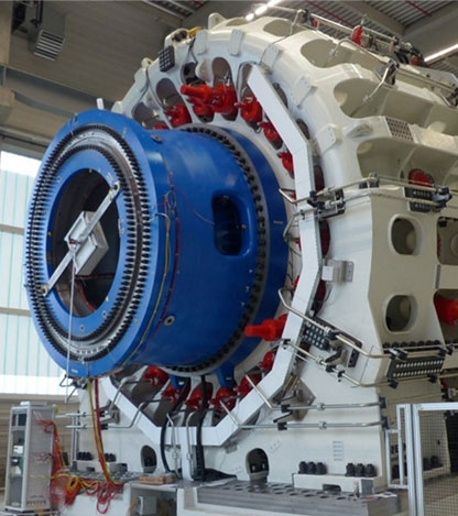
With the Sven Wingquist Test Center, named after the company founder, SKF operates the world's most efficient test center for large bearings in Schweinfurt. The purpose of these test rigs is to validate the performance of large size bearings according to customer specifications, while continuing to acquire knowledge about these bearings by testing them under extreme conditions as close as possible to those encountered in real-world applications.
The Sven Wingquist Test Center: SKF test center for large size bearings
The SKF test center has a full range of test rigs. These test rigs make it possible to carry out tests under a wide variety of conditions:
- Low-speed and high-speed drive (in relation to bearing size).
- Various types of loads can be applied (radial, axial, combined), from bending moments to high amplitude, depending on the requirements of the application for which the bearings are intended.
- Dynamic loading is possible up to a certain frequency variation (large structures).
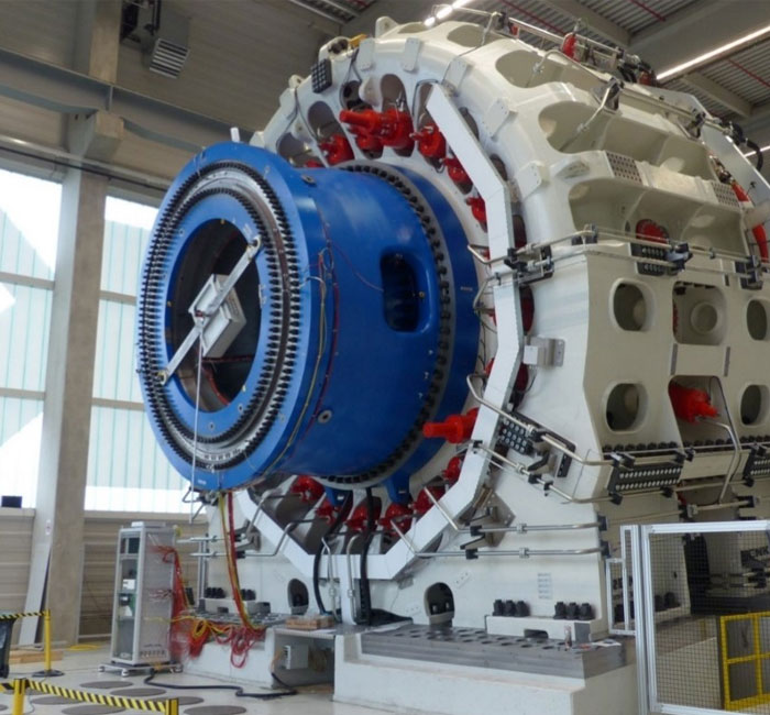
- Validation and development of single wind main bearings and full wind main shaft arrangements (optionally including original customer parts)
- Dynamic application of the high load, especially bending moments, with realistic load scenarios
| Radial load | 8 MN |
| Axial load | 8 MN |
| Bending moment | 40 MNm |
| Load dynamic | Yes |
| Rotational speed | 30 rpm |
| Bearing size | approx. 2 m up to 6 m |
| Lubrication | grease or oil |
| Size of test setup | max. 22x9 m |
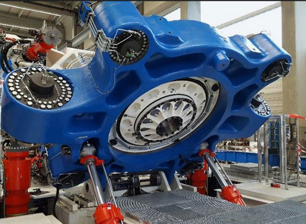
- Dynamic testing for development purposes up to high rotational speeds
- For Large Size Bearings in steel industry, wind, pulp & paper, cement, marine, etc.
- High speed, dynamic load application
| Radial load | 7 MN |
| Axial load | 3 MN |
| Bending moment | 10 MNm |
| Load dynamic | Yes |
| Rotational speed | 250 rpm |
| Bearing size | approx. 1,0 m up to 3,2 m |
| Lubrication | grease or oil |
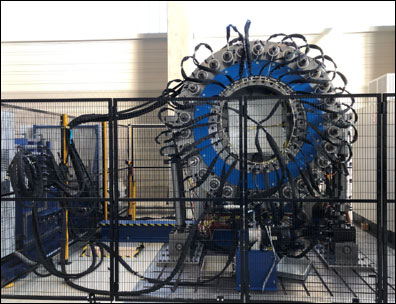
- Static testing for development purposes up to medium rotational speeds with high axial load
- Static testing for all purposes
| Radial load | 1,5 MN |
| Axial load | 20 MN |
| Bending moment | None |
| Rotational speed | 50 rpm |
| Bearing size | up to 3,5 m |
| Load dynamic | None |
| Lubrication | grease or oil |
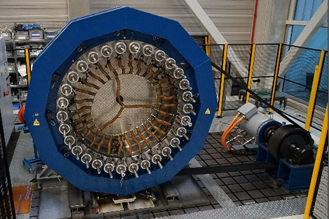
- Static testing for development purposes up to medium rotational speeds with high axial load
- Static testing for all purposes
| Radial load | None |
| Axial load | 12 MN |
| Bending moment | None |
| Rotational speed | 50 rpm |
| Bearing size | up to 3 m |
| Load dynamic | None |
| Lubrication | grease or oil |
As mentioned in the introduction, each of these test rigs require the use of a large number of bolted assemblies, from M24 to M160.
The rigs are all monitored for temperature and vibration, and the bearings are fitted with sensors in the rolling elements to monitor their load and other kinetic variations. A large amount of data is created for analysis, during and after testing.
This test center and the results generated serve as a platform to:
- Close the loop between fundamental research (SKF Research, Technology and Development Center) and verification through in-house and field testing (i.e. sensor roller, new materials, lubrication, etc.).
- Develop and calibrate digital twins by calibrating in-house calculation tools. In-house software ranges from bearing life prediction (microphenomena) to multi-body systems, bearings + environment (macrophenomena).
Safety and reliability have top priority
The installations are fully monitored to collect and process data related to key parameters of the bearings and their components. To carry out these processes successfully, the robustness of the plant assembly must be guaranteed. These installations must be able to withstand the heavy loads and dynamics associated with heavy rotating machinery. Given that these devices contain many large bolt assemblies, the correct installation and durability of these components must be secured for the given test conditions.
Verification of bolted connections: The special challenges of large bearings
Verifying the robustness of bolted assemblies for large machines is quite challenging, particularly when verification using prototypes is not an option. In this respect, numerical evaluation plays a major role in helping to confidently develop the right configuration. Combining these analytical assessments with a long-established guideline, such as VDI 2230, is even more useful. So, it’s easy to imagine the challenges that SKF engineers face in developing accurate models quickly.
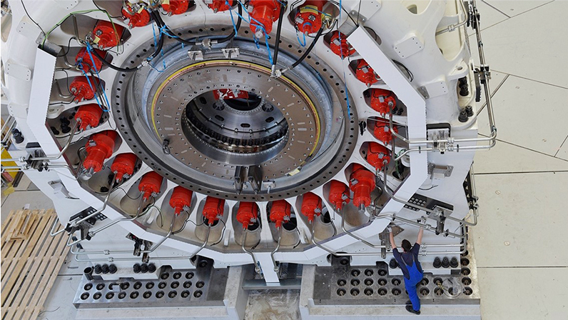
Example from the MSTR test rig development
To illustrate these challenges here is an example of the ongoing development of the MSTR test rig involving numerous bolted assemblies: Transmission to the structure of the load as applied on the test rig (wind power).
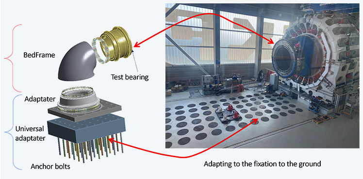
Think of the test rig as the hub and blades on which the wind acts, the wind power, and generates the load on the main shaft bearing. The idea behind this development is to be able to connect our power unit to part of the drive system of a wind turbine. This enhancement will enable the bearings to be tested under conditions even closer to real-world application. To achieve the required configuration, several elements need to be connected together:
- Adapters and bedframe to connect the bearing to the loading unit,
- The adapter and universal adapter to connect the bedframe to the foundation (universal for use with different types of turbine).
There are several bolted assemblies that are large in terms of the number and size of the bolts. Finding the final design requires a reliable and robust structure, and to achieve this, we need to verify the strength of the bolts. Digital evaluation plays a major role in helping to confidently arrive at the right configuration. Even more useful is the combination of these analytical assessments with a long-established guideline, such as VDI 2230. For this, a combined approach is followed.
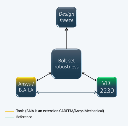
It is therefore important to refer to the long-proven VDI 2230 guideline. This allows us to confidently choose the bolt arrangement (size and number) as well as the initial pretension. It also helps us to choose the best clamping method (precision and cost).
Using simulation, an intelligent model can be developed, providing an overall assessment of each of the many bolts contained in the model.
The classical approach
The following is a brief summary of how to approach the assessment of bolt strength, inspired by the VDI 2230 guideline and then verified by numerical calculations.
Once the size of the bolt has been determined, its free length (between the engagement and the nut) in the event of potential bending must not be ignored, given the variations in the load cases. Then, an initial value of prestress must be specified, which can be set at FMzul of VDI 2230 and adjusted according to the expected results. The purpose of this approach is to obtain the forces and moments acting on the bolt, in order to convert them into safety factors (using the stress level). It is recommended to define a class 3 model, in order to integrate potential bolt deflection (a factor that reduces bolt strength). After calculation, it will be necessary to extract the reaction loads around the bolt head and convert them into stresses, as suggested by VDI guideline 2230.
It is important to mention that the moment acting on the bolt must not be neglected in order to accurately determine the stress in the bolt. This must be done by creating a coordinate system underlying the bolt contact surface. This is the preferred approach to avoid stress singularities due to mesh quality/contact on the bolt, meaning that the more bolts there are, the more effort is required.
Having a model with many sets of large bolts requires time to define and calibrate the model correctly. In order to obtain an accurate assessment of bolt strength, it's not enough to simply display the stress for the individual bolts. For each bolt, the stress resulting from the force and the moment acting on it must be determined for each given load cycle.
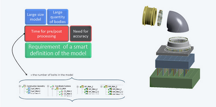
The greater the number of bolts, the more time-consuming it is to obtain a functional model:
- A lot of time is needed to create a coordinate system for each bolt, allowing the force and moment acting on the bolt to be determined.
- A lot of time is needed to create the corresponding output card to extract the reaction forces and moments.
- This operation is repetitive and time-consuming, with a high potential for errors.
Bolt Assessment inside Ansys gives you a reliable, functional model in almost no time.
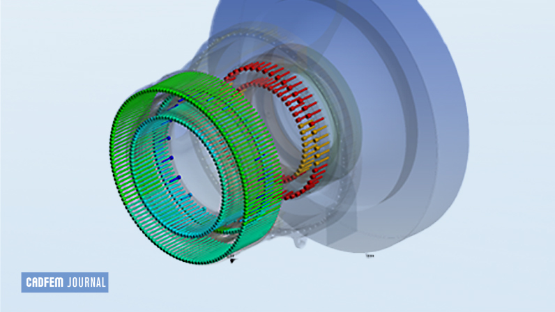
One solution for ensuring a reliable model and making it more functional is to use Bolt Assessment inside Ansys, developed by CADFEM. All the work involved in preparing input and output maps (as shown in figure 5) is automated, which saves an enormous amount of time. In the model containing over 400 bolts, several hours of preparation and extraction of results are reduced to just a few minutes. Below are two different graphical representations. The one on the left shows the stress results obtained with the method described so far to illustrate the static safety coefficient. The one on the right shows the coefficient of safety obtained using the BAiA module. The results are similar between the conventional approach and the BAiA. However, the biggest difference is in the time spent creating the model and post-processing the results (see figure). There is a very good match.
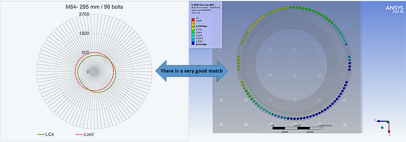
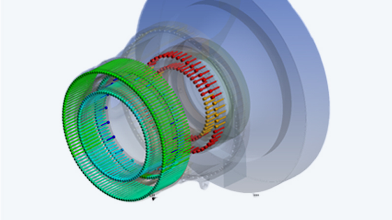
Using BAiA gives you greater confidence and makes it easier to obtain reliable results. Moreover, all the safety factors available in BAiA make this tool reliable, complete and precise, and a perfect digital complement when prototyping is not possible.
Thierry Adane Project Engineer, Test Center SKF GroupCADFEM listened attentively when the problem was raised, and immediately saw the relevance of using BAiA to help us. They provided the training we needed to effectively to solve our task and was on hand to evaluate initial use and results.
CADFEM a long-term partner
It takes years to gain experience and confidence in the development and use of such test rigs. As a young unit, we rely on digital tools such as BAiA to confidently build test rigs, without having to use prototypes which would require a great deal of time and cost to produce (if at all possible). This allows us to accurately verify compliance in accordance with the VDI 2230 directive.
It is the combination of the digital tools offered by CADFEM and the VDI 2230 guideline that allows us to define a robust construction for bolted assemblies, save time and offer our customers proven solutions much more quickly.
The relationship with CADFEM is key in ensuring the most suitable software configuration, practical, case-oriented training, and personalized support. This relationship of quality and trust helps the SKF-engineers to meet customers' requirements as quickly and reliably as possible.

SKF GmbH Sven Wingquist Test Center
https://www.skf.com
Author: Thierry Adane
(SKF GmbH Sven Wingquist Test Center )
Cover Images:
Right: ©Sven Wingquist Test Center
Left: ©Sven Wingquist Test Center
Published: December, 2023
Contact CADFEM


